DiVYA
PHONE : +91-8374485831,
Mail : storagetankshy@mail.com
INDUSTRIAL PIPING DESIGN CONULTANCY SERVICES

Compressor Piping System Design Services
Piping Design Consultants- Compressor Piping system | Divya Engineering
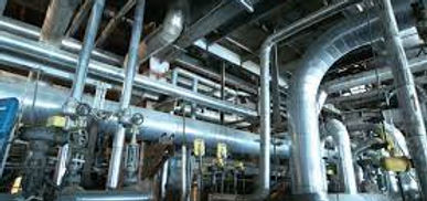
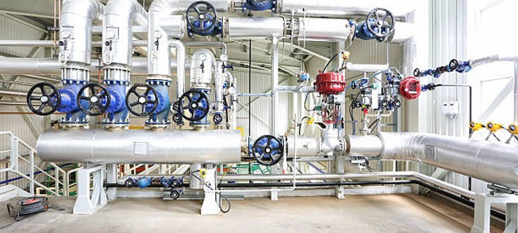
A compressor piping system is a crucial component of an industrial setup, particularly in environments where compressed air or gases are required for a variety of processes. The piping system transports compressed air, gas, or fluid from the compressor to various parts of a facility where the compressed medium is needed. The design and implementation of these systems are essential for efficiency, safety, and performance. Here's an overview of the key components and design considerations for a compressor piping system:
Key Components:
-
Compressor Unit: The compressor itself, which could be rotary screw, reciprocating, centrifugal, or diaphragm. The type of compressor used will influence the piping system design.
-
Air or Gas Receivers: These are large tanks that store compressed air or gas and provide a buffer between the compressor and the piping system. They help smooth out pressure fluctuations and serve as a reserve during peak demand.
-
Filters: Filters remove particulates and contaminants from the compressed air or gas before it enters the piping system, helping to protect downstream equipment from damage and ensuring air quality.
-
Dryers: Compressed air can often carry moisture, which could cause corrosion or freeze-up in the piping. Air dryers remove moisture and help prevent such issues.
-
Regulators: Pressure regulators are used to control the air pressure delivered to the piping system and to various pneumatic tools and devices.
-
Valves: Control valves regulate the flow and pressure of the air within the system. These could include shut-off valves, pressure relief valves, and check valves.
-
Piping and Fittings: These are the pipes, tubes, and fittings that connect all the components of the system. Materials used can include steel, copper, aluminum, or plastic, depending on the pressure and temperature requirements.
-
Manifolds: Manifolds distribute compressed air to different branches of the piping system, ensuring even pressure distribution.
Design Considerations:
-
Pipe Material Selection:
-
Steel: Common for high-pressure systems due to strength and durability.
-
Aluminum: Lightweight and corrosion-resistant but may not be suitable for high-pressure systems.
-
Copper: Often used for low-pressure systems or for specific applications requiring excellent corrosion resistance.
-
-
Sizing of Piping: Proper sizing is essential to ensure that the system can deliver the required flow and pressure without excessive energy loss. Undersized pipes result in higher energy consumption and poor system performance. Larger pipes can handle more flow but may be more expensive.
-
Flow Considerations: The piping should be designed to accommodate the maximum required flow rate, with allowances for future expansion. The piping layout should minimize the number of turns, tees, and elbows to reduce friction losses.
-
Pressure Drops: Pressure drop occurs when air flows through the system, and some energy is lost due to friction in the pipes and components. Proper pipe sizing, smooth pipes, and low-resistance fittings help minimize these losses.
-
Expansion and Flexibility: The piping system should allow for future expansion. It’s also important to have some flexibility in the system to absorb vibrations and thermal expansion.
-
Drainage: Proper drainage is essential to remove moisture that might accumulate in the piping, especially in humid environments. Trap drains and automatic drain valves are often installed at low points in the piping.
-
Maintenance Accessibility: The piping system should be designed with maintenance in mind, providing easy access to filters, valves, and other components that may require regular inspection or servicing.
-
Safety: High-pressure systems must be carefully designed to handle the potential hazards. The system should be equipped with safety relief valves, and all parts of the system should be rated for the maximum operating pressure.
-
Vibration Dampening: Compressors can generate vibrations that, if not properly managed, can lead to premature failure of pipes, joints, and fittings. Vibration isolators are often used to reduce this impact.
-
Energy Efficiency: A well-designed compressor piping system will minimize energy consumption. This includes minimizing pressure drops, using appropriately sized pipes, and incorporating energy-saving technologies like variable-speed drives.
Common Piping Layouts:
-
Ring Main System: In this configuration, the compressed air is distributed in a loop that reduces pressure drop and ensures even distribution.
-
Tree System: A more typical layout where the main pipe branches off into smaller pipes, used for specific equipment or departments.
-
Modular Systems: This approach allows for easy expansion of the piping network as the facility grows or new compressors are added.
Common Issues in Compressor Piping Systems:
-
Leaks: Leaks in the piping can lead to energy loss and decreased efficiency.
-
Corrosion: Over time, moisture and contaminants can cause corrosion in metal pipes, leading to leaks or failure.
-
Blockages: Dirt, scale, or ice can block the pipes, reducing flow and causing system inefficiency.
-
Overpressure: If the system is not designed to handle sudden surges in pressure, overpressure can cause pipe rupture or damage to components.
-
Noise: Compressors and piping systems can generate significant noise, especially when air moves through the pipes at high pressure. Noise-dampening solutions may be necessary.
Conclusion:
Designing a compressor piping system involves many considerations to ensure efficiency, safety, and reliability. It requires careful planning, the correct materials, and a layout that minimizes pressure drops and energy consumption. Regular maintenance and monitoring are essential to keep the system functioning at optimal levels.
"Divya Engineering offers expert piping design consultancy services specializing in compressor Piping systems. We provide innovative and cost-effective solutions tailored to your project needs
COMPRESSOR PIPING DESIGN AND DRAFTING
Divya Engineering is a consultancy dedicated to providing expert design services for compressor piping systems. Their include creating detailed CAD drawings, conducting design calculations, performing pipe stress analysis, and developing 3D models, along with fabrication and erection drawings. The team emphasizes critical elements such as material selection, support detail design, and project management while ensuring compliance with important standards like ASME B31.1 and ASME B31.3. In addition to compressor systems, Divya Engineering serves various industries, including oil and gas, petrochemicals, and power generation, services such as piping layout optimization, support design, stress analysis with CAESAR II, and the creation of Piping and Instrument Diagrams (P&IDs), among others.
COMPRESSOR PIPING LAYOUT AND ROUTING
Divya Engineering's Compressor Piping Design Services encompass a range of essential offerings, including Piping Layout and Routing. This is crucial for the effective design of compressor distribution systems across residential, commercial, and industrial. It guarantees the safe and efficient transportation of fluids through the piping network while addressing space limitations, optimizing system performance, and facilitating maintenance. **Tools Used for Piping Layout and Routing** - AutoCAD: Utilized for both 2D and 3D design, AutoCAD is commonly employed to create compressor piping layouts and routing plans. - Revit: This software is ideal for Building Information Modeling (BIM), particularly for compressor piping systems within structures. - Plant 3D: Designed for industrial compressor systems, Plant 3D assists in modeling routing and optimizing piping configurations.

COMPRESSOR PIPING SUPPORT DESIGN
Divya Engineering's Compressor Piping Design Services encompass a range of essential, including Piping Support Design. This critical aspect of any piping system, particularly within compressor distribution frameworks, ensures structural integrity, operational efficiency, and safety throughout the system's lifespan. The service focuses on creating robust supports, hangers, and brackets that secure the pipes, protecting from potential damage caused by movement, vibration, thermal expansion, and other external factors. To achieve this, advanced software tools such as CAAR II for piping stress analysis and support design, AutoCAD Plant 3D for 3D modeling layout integration, and Revit for 3D visualization in integrated designs are utilized.

COMPRESSOR PIPING MATERIAL SELECTION
Piping Material Selection is a critical aspect of compressor piping design, and Divya Engineering's services likely include assisting clients in choosing the most suitable materials for their compressor systems. Proper material selection ensures that the system is durable, efficient, and capable of withstanding the pressures, temperatures, and other conditions it will encounter throughout its lifecycle. Typically, Piping Material Selection involves evaluating factors such as pressure, temperature, resistance, and cost efficiency. Whether residential, commercial, or industrial applications, selecting the right materials guarantees optimal performance and long-term sustainability. If you’d like to discuss specifics for your projects, feel free to reach.

COMPRESSOR PIPING STRESS ANALYSIS
Piping stress analysis is a crucial component of Divya Engineering's compressor piping design services. This analysis ensures that the system structurally robust and capable of withstanding the stresses it will encounter throughout its lifecycle. In compressor systems stress analysis plays a vital role in identifying potential issues such as thermal expansion, pressure surges, vibrations, and mechanical loads, which could lead to failures, leaks, or degradation of the system. **Industry Standards and Codes for Piping Stress Analysis**Divya Engineering adheres to industry standards during their piping stress analysis, including: - **ASME B31.3:** This standard pertains to process piping systems, outlining the necessary design, materials, and considerations for compressor and industrial piping systems. - **ASME B31.1:** This code addresses power piping encompassing steam, compressor, and fluid systems.

COMPRESSOR PIPING AND INSTRUMENTATION DIAGRAMS (P&IDS):
Divay Engineering Compressor Piping Design Services - Piping and Instrumentation Diagrams (P&IDs): Piping and Instrumentation Diagrams (P&IDs) are vital tools in the design, operation, and maintenance of compressor piping systems. Divay Engineering's Compressor Piping Design Services include the creation of comprehensive P&IDs that ensure clarity and precision in system design, operational efficiency, and ease of future troubleshooting. But what exactly are P&IDs?
A Piping and Instrumentation Diagram (P&ID) is an in-depth, detailed graphical representation of a piping system, showing the relationships between various components such as pipes, equipment, valves, instruments, and control systems. These diagrams are crucial for understanding how fluids flow through the system and highlight key components like compressors, filters, tanks, and associated instrumentation or control devices. By integrating all these elements, P&IDs serve as a blueprint for the entire piping system, ensuring safe and effective operation and simplifying any necessary maintenance or modifications down the line.

COMPRESSOR DEVELOPMENT OF PIPING SPECIFICATIONS AND STANDARDS
When it comes to compressor piping systems, the development of piping specifications and standards is a cornerstone service provided by Divay Engineering. These specifications and standards are essential in ensuring that the entire compressor piping system is designed, installed, and maintained using consistent, reliable, and efficient practices. This approach plays a critical role in guaranteeing the system’s safety, performance, durability, and compliance with both local and international regulations.
Divay Engineering adopts a systematic, phased methodology when developing these specifications and standards, ensuring thorough coverage and success throughout the project lifecycle. This service is particularly vital for compressor piping design, as it ensures the proper selection of materials, accurate pipe sizing, and adherence to local, national, and international standards. By providing detailed and customized piping specifications, Divay ensures that compressor systems operate at their optimal efficiency while maintaining long-term reliability and safety.
COMPRESSOR PIPE SIZING AND HYDRAULIC CALCULATIONS
Divay Engineering's compressor piping design services include key components such as pipe sizing and hydraulic calculations, which are crucial for ensuring the efficiency, reliability, and longevity of the system. Proper pipe sizing and hydraulic analysis are foundational to optimizing the performance of compressor systems across a variety of sectors, including industrial, commercial, and municipal applications.
At Divay Engineering, we employ a comprehensive and methodical approach to pipe sizing and hydraulic calculations, carefully evaluating all relevant parameters to achieve optimal system performance. Our precise calculations help improve flow efficiency, minimize pressure losses, and ensure the selection of the most appropriate materials for compressor applications. By thoroughly analyzing the system’s requirements, we ensure that every aspect of the design contributes to the long-term functionality and success of the compressor piping system, delivering enhanced performance and reduced operational costs.
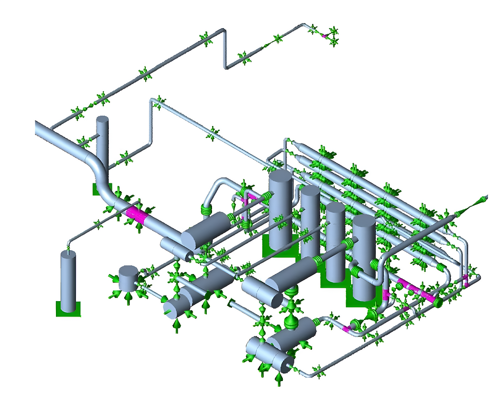
COMPRESSOR 3D MODELING AND DESIGN
In the field of compressor piping design, 3D modeling is crucial for creating efficient, accurate, and visually clear representations of piping systems. Divay Engineering provides advanced 3D modeling and design services to ensure that compressor piping systems are carefully designed, optimized, and executed with precision, significantly reducing the risk of errors or the need for rework.
3D modeling and design are fundamental to modern compressor system design, allowing Divay Engineering to streamline the design process, minimize errors, and ensure that the system is both efficient and cost-effective. The ability to visualize, simulate, and analyze the entire system before construction is a game-changer, helping to identify potential challenges and refine the design for optimal performance in real-world conditions. Whether you're designing a new compressor system or looking to optimize an existing one, Divay Engineering's expertise in 3D design will help ensure a flawless and efficient implementation.

COMPRESSOR ISOMETRIC/FABRICATION/ERECTION DRAWINGS
At Divay Engineering, the development of isometric, fabrication, and erection drawings plays a critical role in the compressor piping design process. These drawings are essential for the successful installation, assembly, and operation of the compressor system. They offer clear, precise, and detailed instructions for the construction team, ensuring that the system is built according to design specifications, industry standards, and safety requirements.
What are Isometric, Fabrication, and Erection Drawings?
Isometric Drawings: Isometric drawings are a type of 3D representation of the piping system, typically drawn at a 30-degree angle to the horizontal. These diagrams visually convey the layout and orientation of pipes, valves, and other components within the system.
Purpose: The primary purpose of isometric drawings is to simplify the visualization of complex pipe layouts, allowing the viewer to understand the system in three dimensions. These drawings are crucial for identifying the placement of key components and ensuring that all parts of the compressor piping system are correctly aligned and easily accessible.
Fabrication and Erection Drawings: These types of drawings provide the technical details required for the physical construction of the compressor piping system. Fabrication drawings show the specifics of each piping component, including materials, dimensions, and assembly instructions, while erection drawings guide the installation team in positioning and assembling the pipes and equipment on-site.
Through these detailed drawings, Divay Engineering ensures that every aspect of the compressor piping system is built with accuracy, efficiency, and compliance with all relevant codes and standards, providing a solid foundation for optimal system performance.
Compressor Piping Design Services
Piping Design Consultants- Compressor Piping | Divya Engineering
Piping Design and Drafting: Creating detailed CAD drawings and design calculations for Compressor piping systems used in power plants, refineries, and other industrial facilities.
Pipe Stress Analysis: Performing static and dynamic stress analysis using software like CAESAR II to ensure the Compressor piping system can withstand operational and environmental stresses.
3D Modeling and Design: Using software such as PDS, PDMS, or Auto Plant to create 3D models of Compressor piping systems for better visualization and accuracy.
Isometric/Fabrication/Erection Drawings: Preparing detailed drawings for the fabrication and installation of Compressor piping systems.
Support Detail Drawing Preparation: Designing and detailing the necessary supports for the Compressor piping system to ensure stability and safety.
Project Management: Managing the entire Compressor piping design project from initial conceptualization through fabrication and commissioning.
Compliance with Standards: Ensuring that the design complies with relevant standards such as ASME B31.1 for power piping and ASME B31.3 for process piping.
BILL OF MATERIAL, INSULATION & EXPANSION JOINTS
Challenges in Compressor Piping System Design
Designing compressor piping systems comes with a range of challenges that require specialized knowledge and attention to detail. Compressor systems are integral to many industrial operations, including manufacturing, HVAC, and power generation, and the piping systems need to be efficient, reliable, and durable under demanding operational conditions. Below are some of the key challenges encountered in compressor piping system design:
1. Pressure Management
Compressor systems operate at varying pressures depending on the application, which presents challenges in maintaining stable pressure levels throughout the piping network. Sudden pressure surges, overpressure, or underpressure can lead to damage in the system or reduce efficiency. Proper pressure regulation is essential to avoid system failures. The design must account for pressure drops across the piping system, ensuring that pressure levels are optimal at each component (valves, filters, etc.), and incorporate safety devices like pressure relief valves and surge tanks.
2. High Flow Rates and Fluid Velocity
Compressor systems often require handling high flow rates, which can lead to issues like increased pipe friction, energy losses, and vibrations. The design of the piping system must ensure that the fluid velocity remains within acceptable limits to reduce friction losses and minimize noise and vibration. If the fluid velocity is too high, it can cause turbulence, erosion, and excessive wear on the pipes and components.
3. Material Selection
Selecting the right materials for the compressor piping system is crucial to ensure that the system can handle the operational conditions without degradation over time. Factors like pressure, temperature, corrosion resistance, and compatibility with the compressed air or gases being transported must be carefully considered. For example, piping exposed to high pressure or corrosive gases may require special coatings, alloys, or corrosion-resistant materials. Choosing the right material ensures long-term durability and prevents failures.
4. Thermal Expansion and Contraction
Compressors often generate significant heat, which causes the piping system to expand or contract as temperatures fluctuate. This thermal expansion can create stresses in the piping system, leading to potential misalignments, leaks, or even failure. Designers must account for these temperature-induced stresses by incorporating expansion loops, flexible connectors, or expansion joints to accommodate the expansion and contraction of pipes, ensuring the system remains intact and functions properly.
5. Vibration and Noise Control
Compressor systems, especially reciprocating compressors, can generate significant vibrations, which can propagate through the piping system, causing fatigue and potentially damaging the system over time. Additionally, noise generated by compressor operation can be a concern for both operational efficiency and safety. The design must consider vibration-damping techniques, such as flexible joints, pipe supports, and vibration isolators. Furthermore, noise-reducing measures, like mufflers or silencers, may need to be incorporated into the design to mitigate these issues.
6. Corrosion and Wear
Piping systems in compressor applications are often exposed to harsh environments, including corrosive gases, moisture, and high temperatures. Over time, this exposure can lead to corrosion, erosion, or wear on the piping and components. For instance, air compressors may deal with moisture-laden air, which can cause internal corrosion in pipes if not properly managed. The design must account for the use of corrosion-resistant materials, coatings, and treatments to extend the lifespan of the system.
7. System Integration and Layout
Integrating the compressor piping system with other components of the facility—such as filters, dryers, valves, and storage tanks—presents a design challenge. The piping layout must optimize flow paths, minimize pressure drops, and reduce energy consumption while ensuring that all components are easily accessible for maintenance and repairs. Poor layout can lead to inefficiencies, increased energy costs, and difficulty in performing routine maintenance tasks.
8. Space Constraints
Many compressor piping systems are installed in confined spaces, such as mechanical rooms or industrial plants, which can limit the available room for proper pipe routing and component placement. Designing a system that fits within the available space while still ensuring optimal performance can be challenging. Designers must carefully plan the layout, taking into account factors such as access for maintenance, system flexibility, and ensuring that the system complies with safety standards and regulations.
9. Condensate Management
In compressed air systems, condensate is generated as air cools down within the pipes. If not managed properly, this condensate can accumulate and cause damage to the system, including rusting of pipes and corrosion of internal components. Proper drainage, condensate traps, and moisture separators must be incorporated into the design to manage condensate effectively and prevent water buildup within the piping system.
10. Leak Prevention
Leaks in compressor piping systems can result in significant operational issues, such as loss of compressed air or gas, reduced system efficiency, or even safety hazards. The design must prioritize leak prevention by ensuring proper sealing at all joints, valves, and connections. This may involve using specialized sealing materials or technologies, such as welded joints, O-ring seals, or flange connections that are specifically designed to withstand high pressure and prevent leakage.
11. Maintenance and Accessibility
Regular maintenance is essential to ensure the compressor piping system operates efficiently over time. The design must allow for easy access to components such as valves, filters, and compressors for routine inspections, repairs, and replacements. Incorporating features such as service ports, removable panels, and easily accessible shutoff valves will make it easier for maintenance teams to conduct necessary checks and minimize system downtime.
12. Compliance with Standards and Regulations
Compressor piping systems must adhere to various local and international standards and regulations to ensure safety and environmental compliance. These standards can include pressure ratings, material specifications, installation practices, and safety measures. Navigating these regulations can be complex, and designers must ensure that the system complies with all relevant guidelines to avoid legal issues or safety risks.
Conclusion
Designing compressor piping systems involves overcoming numerous technical challenges, from managing pressure and flow rates to ensuring proper material selection and system integration. By addressing these challenges with a careful, well-thought-out approach, designers can ensure that the compressor piping system is not only efficient and reliable but also safe, durable, and easy to maintain. A successful compressor piping system design optimizes performance, reduces operational costs, and extends the lifespan of the entire system.
ChatGPT can make mistakes. Check im